Microscope Illumination for Liquid Crystal Observation
When referencing books on biological microscopes for illumination
methods suitable for liquid crystal observation, the standard
illumination method presented is Köhler illumination. However, in
books on polarizing microscopes used in mineralogy, the term Köhler
illumination does not appear. Instead, they introduce orthoscopic
illumination methods and a technique called conoscopic observation
along with its associated illumination methods. Here, we will
explore the relationship between these methods and discuss the most
appropriate illumination techniques for liquid crystal observation.
Illumination in Biological Microscopes
In biological microscopy, "Köhler illumination" is the standard
illumination method. Köhler illumination allows independent control
of the illumination area and the numerical aperture (NA) of the
illumination light, providing a highly uniform illumination
intensity on the sample surface.
In Köhler illumination, the
aperture diaphragm located at the focal plane of the light source
and condenser is conjugate with the aperture plane, while the field
diaphragm and sample surface form another set of conjugate planes.
Since the field diaphragm and sample surface are conjugate,
adjusting the field diaphragm changes the illuminated area on the
sample surface. Moreover, because the aperture diaphragm is at the
focal plane on the illumination side of the condenser, the NA of the
illumination can be adjusted using the aperture diaphragm. As
various points of light from the light source are mixed at the field
diaphragm plane, there is minimal unevenness in brightness,
resulting in a uniformly bright image on the sample surface.
Beyond the objective lens, the aperture diaphragm, the back focal
plane of the objective lens, and the eyepoint above the eyepiece are
conjugate planes. The conjugate plane of the field diaphragm
includes the sample surface, the real image plane formed by the
objective lens, and the retinal plane.
In addition to Köhler
illumination, two other illumination methods, critical illumination
and diffuse illumination, are introduced in biological microscopy
texts. Critical illumination is a method where the light source and
sample surface are conjugate planes, providing ample brightness and
a large NA. However, since the light source and sample surface are
conjugate, if a tungsten lamp is used as the light source, the
filament image of the light source may overlap with the observed
sample. Diffuse illumination involves positioning the condenser's
focal point significantly below the sample surface, resulting in a
widely spread illumination at the sample surface. This method
provides high uniformity in brightness, but the illumination has a
low NA and reduced light intensity. Direct irradiation using the
light source without the use of condensing lenses is also a type of
diffuse illumination.
In biological research, polarizing
microscopes are used to visualize transparent structures, requiring
high resolution; therefore, high NA Köhler illumination, similar to
that used in standard bright-field observation, is necessary. As
will be discussed later, the colors observed in polarized light can
change depending on the NA of the illumination light. However, in
biological observations, polarization is used to visualize colorless
samples with small optical path differences (OPDs), so the color
changes are not considered problematic.
Illumination in Mineral Microscopy
Textbooks on polarizing microscopes used in mineralogy describe
two main illumination methods. One is for orthoscopic observation,
where illumination with parallel light rays (NA = 0) is recommended.
The other is for conoscopic observation, which requires high NA
illumination comparable to that of the objective lens. However, it
is unclear whether this is Köhler illumination, critical
illumination, or another method, as I have not seen a detailed
explanation on this matter.
For example,in Tsuboi's "Polarizing Microscope", a faouse
Japanese textbook, it states that the top lens should be removed for
orthoscopic observation and inserted for conoscopic observation.
With the top lens removed, the NA of the illumination system is at
most around 0.2, and the focal point is significantly above the
stage surface. When the top lens is inserted, the NA can reach
around 0.9, and the focal point is approximately 1 mm above the
stage surface.
With the top lens removed, even if you adjust
the position of the field diaphragm of the illumination system, it
is not possible to form a field diaphragm image near the stage
surface, so Köhler illumination cannot be achieved. Furthermore,
even if Köhler illumination were possible, with the top lens
removed, the condenser's NA would still result in low-NA
illumination.
Orthoscopic observation is conducted under
low-NA illumination because, in birefringent materials, the optical
path length and birefringence differ between normally incident light
and obliquely incident light, leading to variations in the
polarization colors. Using high-NA illumination would mix different
polarization colors, making it difficult to distinguish the
characteristic colors of the sample.
On the other hand,
conoscopic observation involves observing the polarization colors
corresponding to the optical path differences (OPDs) of light
passing through the sample at various angles. Therefore, the NA of
the illumination light needs to be similar to that of the objective
lens.
Below figures show conoscopic images (left) and orthoscopic
images (right) of the same sample observed under low NA
illumination. With low NA illumination, the colors observed in the
conoscopic image are almost monochromatic, and the orthoscopic image
shows similar hues.
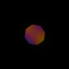 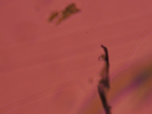
Fig. x Conoscopic (left) and orthoscopic (right) images under
low NA illumination.
In the high NA conoscopic image, colors
different from the center are visible at points away from the
center. Meanwhile, the orthoscopic image becomes a composite of all
these colors, resulting in a nearly neutral color. If the NA of the
illumination is increased to enhance resolution, the colors may
change in ways that make them incomparable to standard polarization
color charts.
 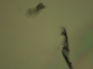
Fig. x Conoscopic (left) and orthoscopic (right) images under
high NA illumination.
Illumination for Liquid Crystal Observation
生物系と鉱物系の照明は上述にように根本的に異なったものです。では、液晶系の照明はどのようにすべきでしょうか。液晶の組織観察の照明で注意すべきことは、斜入射光による見え方のずれを起こさないようにすることです。
As discussed, the illumination methods for biological and mineral
observations are fundamentally different. So, what should be the
approach for liquid crystal observation? When illuminating liquid
crystals for structural observation, it's crucial to avoid image
change caused by oblique incident light.
For horizontally
aligned cells of optically uniaxial rod-like nematic liquid
crystals, the OPD decreases as the optical path length increases due
to the reduced birefringence of oblique incident light within the
plane defined by the director and the microscope's optical axis.
Conversely, in planes perpendicular to the director, oblique
incident light increases the OPD because the optical path length
increases without a change in birefringence. The overlap of colors
corresponding to increasing and decreasing OPDs broadens the
spectral width, reducing color purity. However, unless the NA is
significantly large, there shouldn't be a drastic change in color.
On the other hand, in cases of pronounced biaxiality, such as in
the SmCA phase, the color can change significantly due to oblique
incident light. Even in uniaxial cases, where the molecules are
slightly tilted from perpendicular to the substrate, the situation
differs greatly. Consider the scenario where the SmA phase,
vertically aligned, undergoes a second-order transition to the SmC
phase. As the SmC phase transition occurs, the molecular long axis
tilts from the microscope's optical axis, and Schlieren textures
become observable under parallel light illumination. However, if the
NA of the illumination exceeds the tilt angle of the SmC phase, not
only does the contrast of the Schlieren texture decrease, but the
four-brush defect may also appear as a faint two-brush defect.
From this, it seems that, like mineral observations, low NA
illumination is preferable for observing liquid crystal structures.
But is it sufficient to remove the top lens of a swing-out condenser
and use diffuse illumination? There may be cases where it is
necessary to precisely limit the illumination area, in which case
Köhler illumination may be preferable. Specifically, when observing
thin films with low OPDs, it is necessary to limit the illumination
area to prevent scattered light from regions outside the observation
area from interfering with the observation.
For typical
swing-out condensers, inserting the top lens allows Köhler
illumination, but this reduces the working distance of the condenser
to about 1 mm, making it difficult to use Köhler illumination with a
hot stage. To perform Köhler illumination with a hot stage, a
long-working-distance condenser compatible with the hot stage is
required. For example, with Mettler's hot stage, the distance from
the bottom of the hot stage to the sample contact surface is 15 mm.
Considering the thickness of the slide glass, a condenser with a
working distance of at least 16 mm is needed. There are very few
condensers with a working distance of 16 mm or more. However, if you
are a Nikon Optiphot user, you can attach a long-working-distance
condenser designed for Diaphot, which has a working distance of over
20 mm. While new ones are not available, you can find used ones at a
reasonable price.
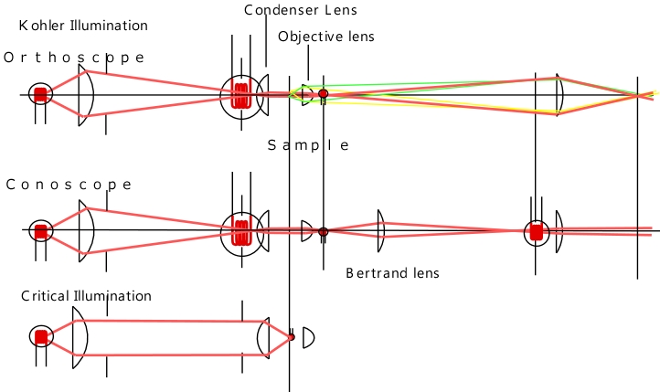
Conoscopic Observation and Köhler Illumination
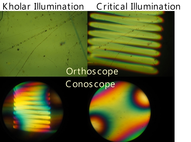
Fig. x Images under Köhler and critical illumination
There is
another issue when using Köhler illumination for mineral or liquid
crystal observation. The following images show orthoscopic and
conoscopic images under Köhler illumination and critical
illumination. Under Köhler illumination, the orthoscopic image has
uniform illumination with minimal unevenness. In contrast, under
critical illumination, the image shows overlapping images of the
light source filament. On the other hand, the conoscopic image under
Köhler illumination shows overlapping light source images, while
under critical illumination, it is uniform. As shown in the figure,
the conoscopic image is an observation of the image at the back
focal plane of the objective lens through a Bertrand lens, but this
position corresponds to the light source image in Köhler
illumination. To eliminate unevenness in these images, a light
source with a large area and uniformity should be used, or a
diffusion filter should be inserted in the illumination optical
path.
|