Numerical Aperture and Resolution
The magnification of a
convex lens is the ratio of the distance from the object to the lens
and the lens to the image. As the object approaches the focal point
of the lens, the ratio increases without limit. If the focal length
of the microscoope objective lens is sufficiently short, it seems possible to
magnify not by a factor of 1000, but by a factor of
10,000 or more.
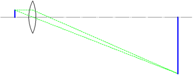
Fig. 1. Enlargement
of a geometrical optical image. The magnification can be increased
without limitation.
It is true that the magnification can be
increased. However, since light also has a wave property, even if
the magnification is increased, it is not possible to accurately
observe fine parts without limitation. Now, how fine a structure can
be accurately observed. The size of the fine structures (resolution
d (nm)) that can be identified by observation with light of
wavelength λ (nm) using an objective lens with numerical aperture
(NA) is
d=αλ/NA …………(1)
where α is a constant of the
order of 1. The NA is defined as
NA = n sin θ (2)
using the angle θ formed by
the optical axis in a focused state and the light beam passing
through the outermost periphery of the objective lens. Here, n is
the refractive index of a medium between the front surface of the
objective lens and the sample. In the case of a dry objective lens,
it is the refractive index of air (=1), and in the case of an oil
immersion objective lens, it is the refractive index of an oil
immersion liquid (about 1.5). Since the maximum value of sin θ is 1,
the maximum value of NA of the dry objective lens is 1. In general,
the higher the magnification of the objective lens, the larger the
NA. When comparing the achromat and the apochromat, the NA of the
apochromat is larger at the same magnification.
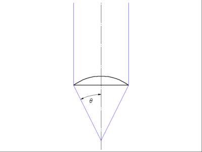
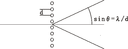
Fig. 2
The sine of the angle θ formed by the light beam passing through the
optical axis and the outermost periphery of the lens when in focus
is the numerical aperture.
Since NA is less than 1 for
a dry objective lens and less than 1.5 for an oil immersion
objective lens, Eq. (1) shows that the limit of the smallest
structure that can be observed with an optical microscope is the
order of the wavelength of the light used for observation.
NA and microscopy resolution
Here, we will explain the
physics behind Eq. (1) based on the derivation by Abbe. The physical
background of Equation (1) is shown using the observation image of a
cross grating. The cross grating of 196 lines/mm was used. The first
order diffraction angle of the grating for 550 nm light is 6.2
degrees, and corresponding NA is about 0.11.
dsinθ=mλ …………(3)
Abbe found that to observe a
diffraction grating image under a microscope, at least the first
order diffracted light must be captured by the objective lens
together with the zeroth order light. In other words, a diffraction
grating image can be observed only with an objective lens whose NA
is greater than the sine of the first order diffraction angle of the grating.
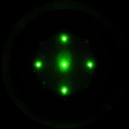
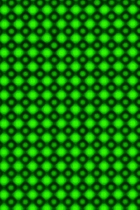
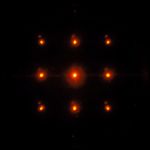
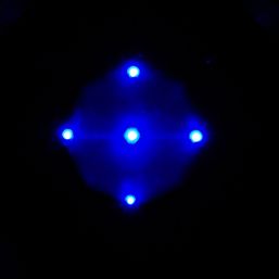
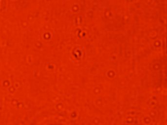
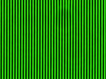
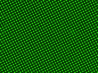
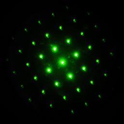
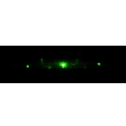
Below is the cross
diffraction grating image and the diffraction pattern image at that
time. If you want to know how the diffraction pattern was
photographed, please see the "Objective lens back focal plane and
Bertrand lens" part near the end of this text.
 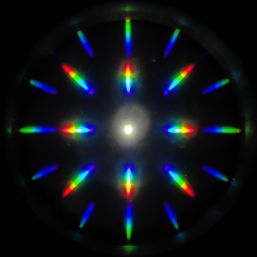
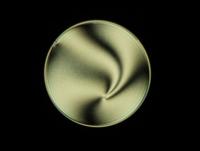
Fig. 3 Cross diffraction grating and its diffraction pattern
The white spot at the center
of the diffraction pattern on the right is the 0th-order light that
went straight without diffraction. As can be seen from the figure,
the 1st order diffraction includes the entire visible spectrum from
blue to red, but the red part of the diffracted light is not
captured at the outer periphery. We can continue the discussion as
it is, but we decided to use a monochromatic filter to make things
simple..
 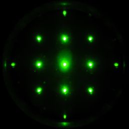
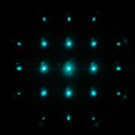
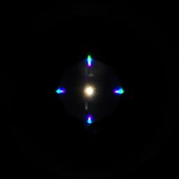
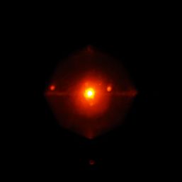
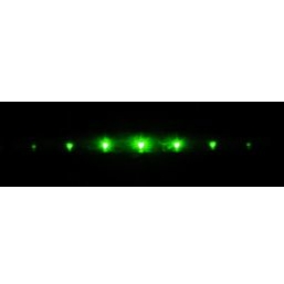
The elongated diffraction spots have become
circular, which is due to the incident light being of a single
wavelength. Additionally, some of the diffraction spots that were
present when using white light have disappeared, and this is because
the diffraction angle for the monochromatic light used is larger
than the NA of the objective lens.
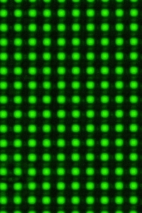
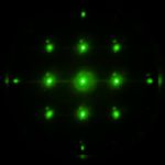
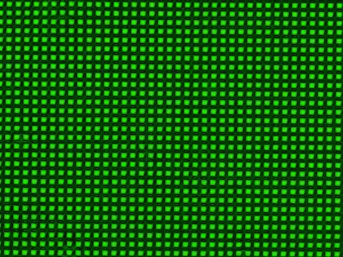
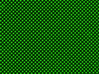
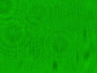
In this state, the original diffraction
grating image is clearly visible as well. From this point, let's
reduce the NA of the objective lens and observe how the diffraction
spots and image change.
 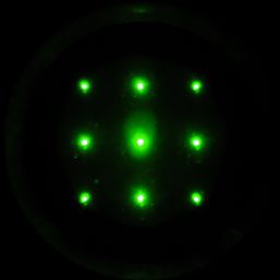
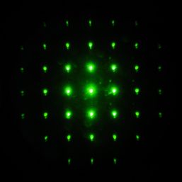
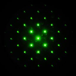
Although the second order spots in the
horizontal and vertical directions of the diffraction pattern are no
longer present, the grating image still appears.
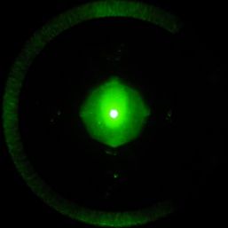
Further limiting the
incident light, only the 0th-order and the 1st-order diffracted
light pass through, and the grating structure is still visible.
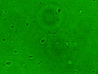 
When the remaining
t1st-order diffracted light are not allowed to pass through, the
grating structure disappears. This change is dramatic. However, a
closer look shows that the pattern of the grating structure changes
as the number of passing spots decreases. The left figure includes
the second order diffraction from the left, the center figure
includes the remaining oblique diffraction, and the right figure
includes only the first order diffraction from the top, bottom,
left, and right. In the second-order case, a clear square grid is
visible. Without second-order diffraction, the bright corners become
rounded, and the grid appears less defined. The first-order-only
image shows a structure resembling a collection of perforated
circles.
This simple observation
shows that in order to observe a periodic grating structure, the
first-order diffracted light must be captured by the objective lens. From
the equation for the period of the stripe structure and the
diffraction angle ((3)), we can conclude that the finest interval d
of periodic structures that can be observed with an objective lens
of numerical aperture NA is
d=λ/NA …………(4)
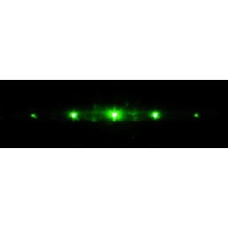
Different wavelengths at the same grating spacing result in
different diffraction angles. Figure shows the diffraction patterns
for 450, 500, 550, and 600 nm light. The diffraction patterns that
were visible at 450 nm and 500 nm are lost at 550 nm and 600 nm.
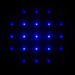   
We stitch the patterns at 450 nm and 600 nm together. The yellow
circle corresponds to the NA of the objective lens.
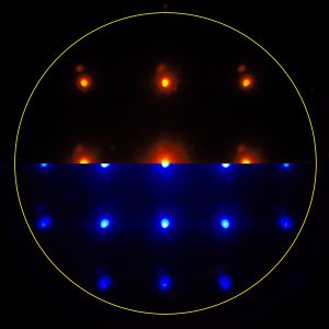
For structures close to the resolution limit, diffracted blue light
also enters the objective lens, but red light does not.
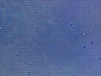 
The images are adjusted to allow only blue light (from the blue part
of the spectrum) to be captured by the objective lens. And in the
next photo, blue and red filters are inserted on the illumination
side.
As expected, the periodic structure shows better contrast with
blue light than with white light, but not observed with red light.
Improvement of resolution by oblique illuminatio
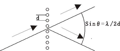
Fig. X
Diffracted light at oblique incidence, in
which the diffraction angle is taken up by the objective lens to
twice that at normal incidence.
As shown in this figure,
when the illumination light is applied at an angle close to the NA
of the objective lens, the first order diffracted light, which was
not captured at normal incidence, can be captured through the
opposite edge of the objective lens.
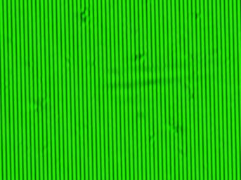 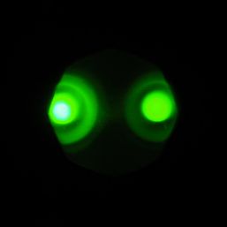
Fig. X:
Image of oblique lighting with first order diffracted light in one
direction (left)
By introducing oblique illumination for zero-order light, the
periodic structure is observed in the direction in which the first
order diffracted light is taken in. However, the periodic structure
cannot be reproduced in the direction in which only the 0th order
light is taken in, which is perpendicular to the first order
diffracted light. Therefore, it is observed as a lattice of vertical
stripes even though the real thing is a square lattice.
When
the 0th order light is incident obliquely, as shown above, the
resolution in the direction of the oblique incidence is improved by
up to twice as much as that in the direction of the normal
incidence. This is a conventional technique called oblique
illumination, which was a common illumination technique for research
microscopes until the 1960s.
Change in image by restriction of incident light
As shown above, when an image is formed only with
diffracted light in a specific direction, an image different from
the original structure is formed. In the example above, the period
that appeared was the same as that of the original lattice, but when
a specific diffracted light is selected by attaching a mask with a
slit on the front surface of the objective lens, a different
structure appears.
The upper image shows the cross-grating image without the mask.
The lower image shows the cross-grating image with the mask so that
the vertical diffraction spots do not enter. As in the case of
oblique incidence, only one direction of the diffraction spot is
taken in, so it is not a cross-grating but a simple vertical
stripe. The period of the stripe is the same as that of the
cross-grating.
Next, the cross-grating is rotated by 45 degrees. When you look
at the image without the mask, the spots diffracted in the diagonal
direction of the cross-grating spread in the horizontal direction.
Only the spot in the diagonal direction is selected by the slit in
the lower image. As in the first image, it is a vertical stripe, but
the period of the stripe is shorter than that of the cross-grating.
Although it is different from the direction of the original
cross-grating, you can understand what period is read from the
original image rotated by 45 degrees.
The last one was rotated about 30 degrees. You can see which diffraction spot
was picked up by looking at the image above. Because of the large diffraction
angle, the period of the stripe that appeared is shorter than 45 degrees
rotation. The contrast of the stripe is reduced because only the first order
diffraction light was picked up.
Coherent Illumination and Incoherent Illumination
The discussion above is based on coherent illumination
conditions, but most of the discussion on microscope resolution is
based on incoherent illumination conditions. There are many
discussions on incoherent illumination on the Web, so please take a
look.
Objective lens back focal plane and Bertrand lens
The figure shows the optical path when observing a double slit
(the slit extends to the paper). The upper part of the figure is an
ordinary observation, in which light from one side of the slit and
light from the other side are formed as enlarged images on the image
plane. In the double slit, interference occurs, and the light
passing through the double slit repeats a light and dark pattern. In
the figure, light traveling straight (zero order light) and light in
the direction in which it first becomes bright (first order light)
are drawn. For each direction, light passing through different slits
is incident on the objective lens in parallel, so that the image is
formed at the focal position (back focal plane) of the objective
lens. By observing the image on this plane, an interference image of
light and dark stripes can be observed.
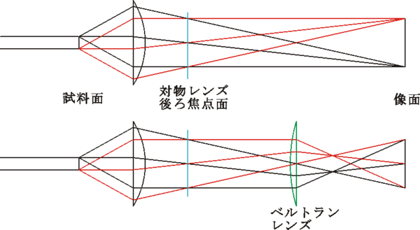
Fig
X: Optical path diagram during normal observation and optical path diagram when
a Bertrand lens is inserted
Some polarized light microscopes are equipped with a "Bertrand lens". When
this lens is inserted into the optical path, the image of the back focal plane
is formed on the normal image plane. The interference image can be observed
directly. Even in a microscope without a Bertrand lens, the image of the back
focal plane can be observed, although it is small, by removing the eyepiece and
looking into the lens barrel. A large image can be observed by using a centering
telescope (an eyepiece used for adjusting the ring of a phase contrast
microscope). The image that can be observed with a Bertrand lens is called a
"conoscopic image" in the industry. In contrast, the magnified image of a normal
sample is called an "orthoscopic image".
|