Visualization of Low Birefringence Samples
Introduction
Since the birefringence of many liquid crystals is around 0.1 or more, if the cell thickness is several microns,
retardation(Optical path difference; OPD) will be large enough to make sufficient contrast for observation under a polarized-light microscope. However, if the sample is thin or
nearly homeotropic alighment condition, the OPD will be less than a few tens of nanometers, making it dark and difficult to observe.
A sensitive color plate has long been used to observe minute OPD samples. The sensitive color plate is a retardation plate with an OPD of about 530 nm.
Its polarization color is reddish purple. When a sample with an OPD of several tens of nm overlaps with the plate, the color changes to blue
and yellow n additive and substractive overlaps. Allowing even small OPD areas to be observed clearly.
Here, we will cover methods for observing small OPD
samples, including precautions when using a sensitive
tint plate.
Sencitive color plate
The typical OPD value of the sensitive color plate is 530 nm. The color change due to the superposition of the phase plates occurs regardless of the OPD value of the original phase plate. However, it is said that the color change caused by the addition / subtraction of the small phase difference can be recognized with high sensitivity when the OPD of the base phase plate is around 530 nm.
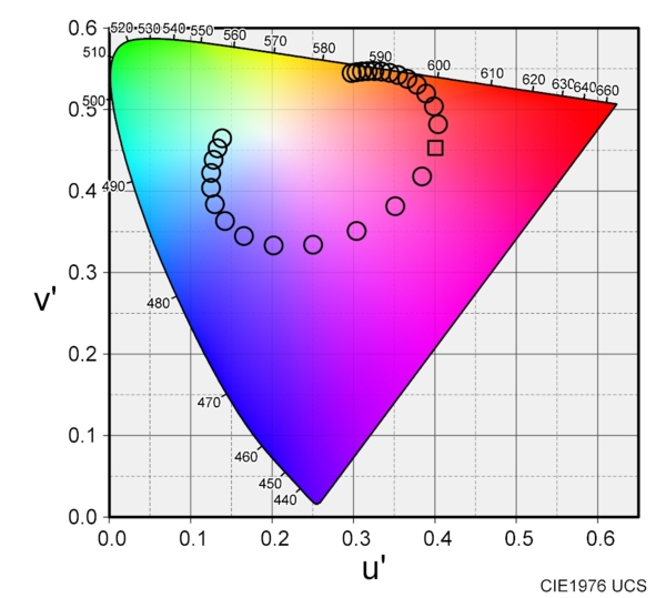
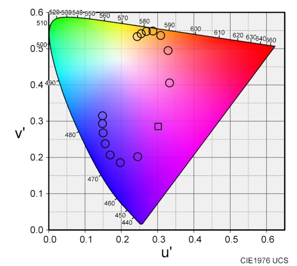
Here, the color change at the OPD value of the original phase plate of 530 nm and other OPD values is calculated and
plotted on the chromaticity diagram as shown in Fig. 1. The D65 light source (daylight) spectrum
was used as the light source..

The circles and square in the figure are plots of color coordinate
values for OPD values of 400 nm to 660 nm in increments of 10 nm,
and OPD of 530 nm is marked with the square. The color differences that can be seen in the chromaticity diagram are not uniform, so it is a little difficult to judge from this figure alone. However, if the OPD value is 530 nm or slightly smaller (the upper side on the chromaticity diagram), it can be seen that the change in color coordinate values with respect to the OPD change is large (that is, the sensitivity of color separation is high).
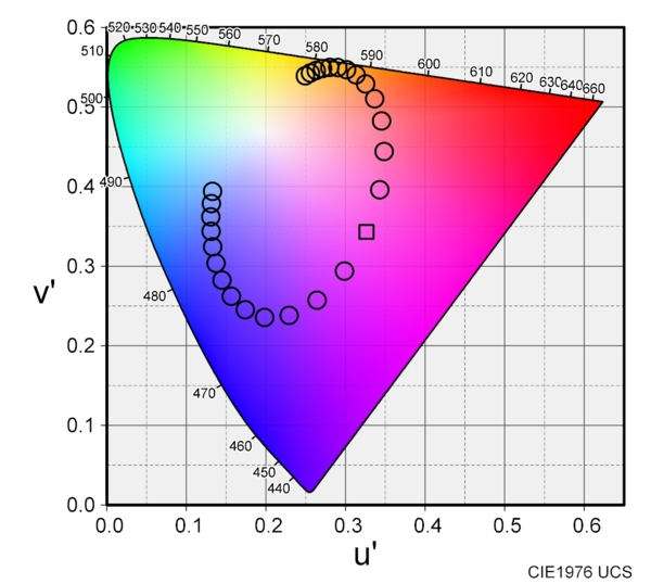
The OPD value of the sensitive color plate used to be around 570 nm. The calculation in Figure 1 is under the D65 light source as described above, but using the A light source (lamp light), the result is as shown in Figure 2.
In this case, the sensitivity is higher around an OPD value of 570 nm rather than 530 nm. In fact, in "Measurement of Sensitive Colors: K. Shimizu, Ohyo-Buturi, Physics, Vol. 25, p. 217 (1956) in Japanese," measurements were performed using a tungsten projector lamp with a color temperature of 2827K, approximately considered as
the CIE-A light source, and it was reported that the highest sensitivity was around an OPD value of 585 nm.
The calculation results for a D50 light source, which lies between the CIE-A and D65 light sources, are shown. In this case, visually, the change in color coordinate values in response to OPD variations appears to be the largest when the OPD is 530 nm.
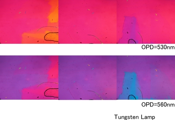
As a light source for microscopes, tungsten lamps were used without color temperature correction filters. Since the CIE-A light source is that of a tungsten bulb with the color temperature of 2855K, it was reasonable to set the OPD value of the sensitive color plate to 570 nm during the era when tungsten lamps were used directly as the light source. When microscope photography began to be taken on color films, general color films assumed daylight illumination. Therefore, color temperature adjustment filters were used to make the illumination light daylight, necessitating a change in the OPD value of the sensitive color plate. This transition occurred in the 1950s, and H. Kubota and others pointed out that when using daylight as the light source, 530 nm provided better discrimination than 570 nm, leading to the shift to 530 nm.
Image recording has changed from film to digital. If you set the color temperature setting of your digital camera to a light bulb color, you can take color pictures using a halogen tungsten light source without using a color temperature conversion filter. Since the filter cause light loss, there is an advantage of not using the filter. However, when using the sensitive color plate for visual observation, it is necessary to recognize that the sensitivity of sensitive colors has deteriorated if the color temperature conversion filter is not inserted.
Hypersensitive Polarization Color Plate
H. Kubota proposed an ultra-sensitive color plate method using a retardation plate with an OPD of 265 nm as a method to improve the discrimination sensitivity of a sensitive color plate by about 2 times (H. Kubota, J. Opt. Soc. Am., 41, 537 (1951)). The OPD value of 265 nm is half of the OPD value of the normal sensitive color plate. Even if this retardation plate is inserted between crossed nicols, it becomes only white with almost no coloring. In this state, even if a sample with a minute OPD is superimposed, the contrast may change slightly, but the difference cannot be recognized.
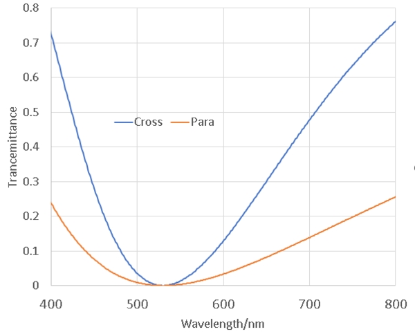
Kubota's proposal is to set the polarizers in parallel instead of crossed. Under parallel polarizers, a sample with small OPD appears as low contrast white, making it impossible to confirm the presence or absence of OPD. However, when a 265 nm retardation plate is inserted in the direction of 45 degrees, the background has almost the same color tone as that of a cross polarizers combined with the sensitive color plate. Figure 4 shows the transmission spectra when a 530 nm sensitive color plate is inserted in the crossed polarizers and when a 256 nm retardation plate is inserted in the parallel polarizers. In both cases, the wavelength at which light does not transmit is the same.
In this situation, consider stacking a phase plate with an OPD value of 10 nm. In the case of cross polarizers, the wavelength that extinguishes shifts by 10 nm. In contrast, for parallel polarizers, since the extinction wavelength is twice the wavelength of the retardation plate, if the wavelength is shifted by 10 nm from 265 nm, the quenching position is shifted by 20 nm from 530 nm. The shift amount is doubled. It is true that it is a method with double sensitivity. The color coordinate change of the ultra-sensitive color method is shown in Fig. 5.
The color coordinate change is plotted when the OPD is increased or decreased by 10 nm with respect to the reference OPD. The coordinate change is approximately double that of the normal sensitive color plate.
An OPD265nm retardation plate is required for the hyper sensitive color plate method. While it seems necessary to custom-order a 265 nm retardation plate. Fortunately, it is easy to find a 266 nm retardation plate on the market. This wavelength corresponds to 1/4 of the wavelength of a YAG laser with a wavelength of 1064
nm. It is commercially available as a quater wave plate of a YAG laser or a 532 nm
half wave plate, which is the SH wave of a YAG laser. It cannot be
inserted into the slot for the retardation plate of a polarizing
microscope, but it can be placed above a condenser. The difference in appearance between the normal sensitive color plate and the hyper sensitive color plate is shown below together with the image without the sensitive color plate.
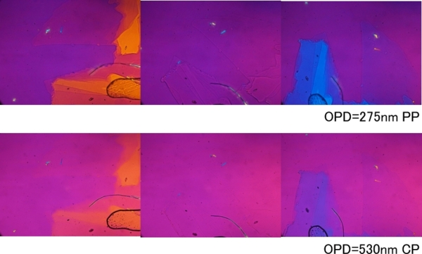
Comparing the image of the sensitive color plate with the image of the hyper sensitive color plate, it is true that the hyper-sensitive color plate has a larger color change and the change can be clearly observed.
Method using a sensitive color plate at a small angle
The orientation of the sensitive plates is set at 45 degrees with
respect to the polarizer, but Newton et al. reported that if the
orientation of the sensitive plates is set at 10 degrees or less
with respect to the polarizer, minute OPD samples can be observed
with high sensitivity.[R.
H. Newton, J. P. Haffegee and M. W. Ho, Polarized light microscopy for
weakly birefringent biological specimens, J. Microscopy, 180, P127(1995).].
The phase plate slot of a polarizing microscope is set at 45
degrees from the axis of the polarizer. There is no rotation
mechanism in the slot slot, so it is necessary to set the polarizer
and analyzer by rotating them from their original angles. By
calculating the color coordinate values with this method, it can be
confirmed that the smaller the angle between the polarizer and the
phase plate is, the larger the change in the color coordinate values
becomes for the same phase difference change. In the figure, filled
square is
the color coordinate value when a sensitive color plate is inserted
in the 45 degrees direction, and open ciercle is the color coordinate change
when a sample of OPD10nm is inserted and the phase plate angle is
changed. The phase plate angles are moved to 45, 30, 15, 10, 7.5, 6,
5,. 1. The sensitivity is almost the same when the angle is changed
from 45 degrees to 30 degrees, but when the angle is changed to 15
degrees, the sensitivity becomes almost the same as that of the
ultra-sensitive touch method, and the sensitivity becomes even
better at a smaller angle. 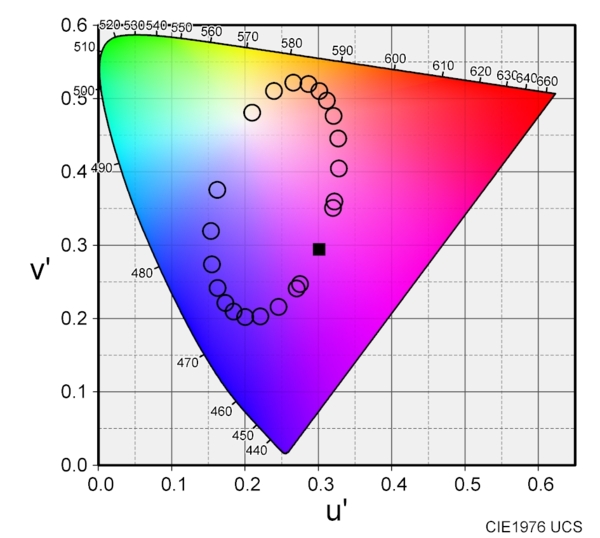
However, when the angles of the axes of the polarizer and the
retardation film are close, the amount of transmitted light is small
and the image becomes dark, making observation difficult. The
angular dependence of the brightness index is shown below.
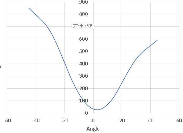
At 15 degrees or less, which is more sensitive than the
ultra-sensitive color method, the brightness is less than 1/3 of the
brightness when the sensitive color plate is inserted at 45 degrees.
This figure was created with the OPD of the sample at 10 nm.
However, if the OPD of the sample is smaller, it becomes even darker
and it becomes difficult to confirm the color by visual observation.
The following shows the image when the sensitive color plate is
inserted at 3 degrees and 10 degrees with respect to the polarizer.
The sample is the same as the above-mentioned sensitive color /
ultra-sensitive color plate.
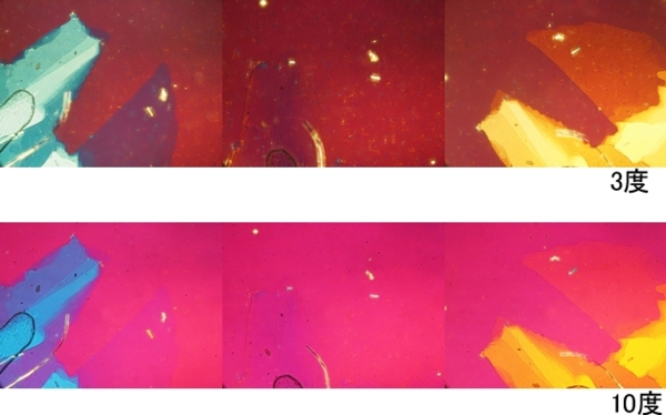
In each photograph, the contrast is higher than that of the sharp
color / ultra-sharp color, but it is too dark to observe visually.
It is necessary to observe the image from the image sensor whose
sensitivity is adjusted.
Rectifirer
|